The VMARS Collins 618T Special Interest Group (SIG)
Introduction
The Collins 618T SIG was formally established in April 2012, with main aims, to help those assembling a station to get on the air, to use the set on the air, and to make available documentation relevant to the 618T.
Technical Overview
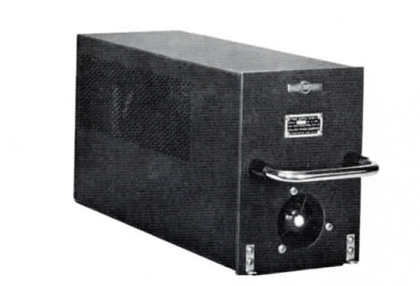
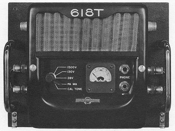
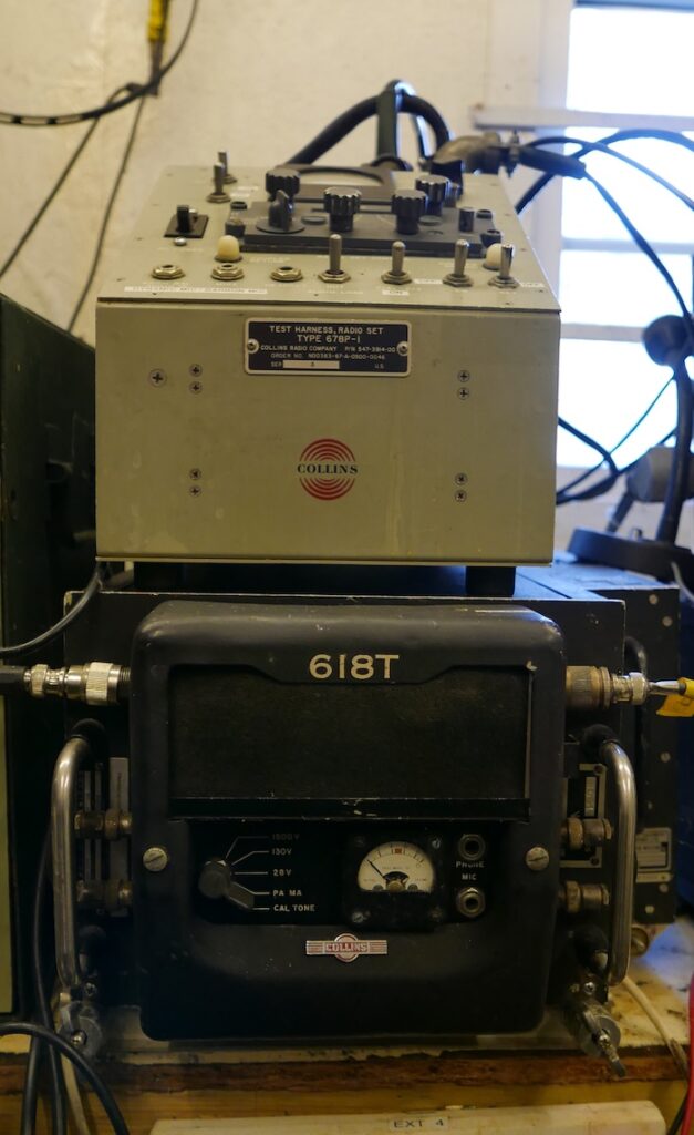
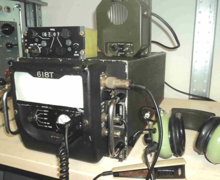
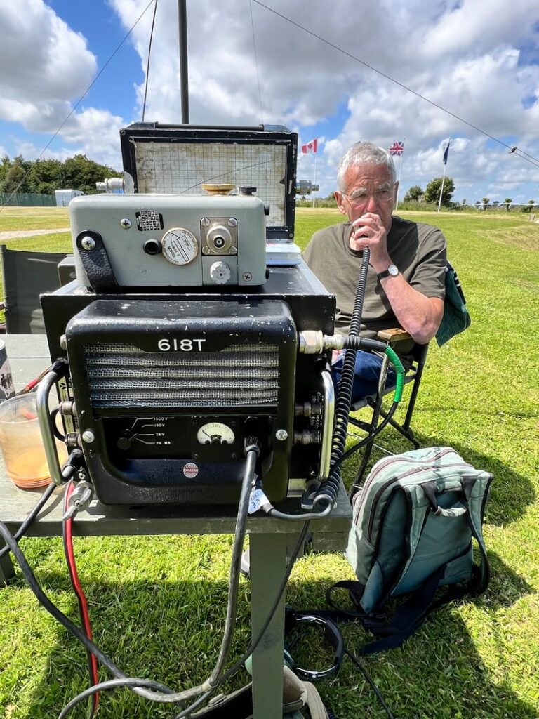
The 618T is a 400 W SSB/125 W AM HF aircraft transceiver. The set covers the frequency range 2 to 30 MHz in 1 kHz steps. The 618T covers several modes of operations: USB, LSB, AM, CW and DATA. The AM mode uses the upper sideband with the carrier re-inserted for compatibility with older equipment only capable of AM. The operating frequency is crystal-controlled and stabilised to within 0.8 part per million. Transmit output impedance is 52 Ω unbalanced with SWR not to exceed 1.3:1. The tuned circuits and output circuit are tuned automatically by an ‘Autopositioner’ and a servo motor with an average tuning time of 8 seconds (excluding the tuning time by external tuners). The power amplifier consists of two parallel-connected beam power tetrodes 7204 (4CX250F) driving a π-network. A servo motor drives a roller coil to tune the tank circuit. The receiver has a sensitivity of 1 μV on SSB and 3 μV on AM. Four meter selector switch positions on the front-panel are used to check power supply voltages and power amplifier plate current. The 618T uses a hybrid approach with 90 transistors and 14 valves.
History
The 618T was made by the Collins Company in the US in the early 1960s and probably still in use today. From the serial numbers, it is obvious that many thousands were manufactured. Main versions were the military AN/ARC-94, 102, 119 and 120 versions and the civilian 618T-1, 618T-2 and 618T-3 versions.
In civilian aircraft it was known as the 618T. It was used extensively in RAF and Fleet Air Arm aircraft, and known as the M5. It was also used in the Army, and known as the C15. Many of the sets on the UK surplus market came from surplus MOD stock. The 618T has always been relatively cheap to buy, probably because of the difficulty in obtaining the connectors and control boxes. However, these parts do appear on the surplus market, and once in possession of the parts, getting the set on the air is relatively simple matter, despite the complexity of the set.
The Collins 618T is considered an iconic and highly innovative high-frequency (HF) single sideband (SSB) aircraft transceiver. It was a revolutionary piece of equipment in the field of aviation and military communications, known for its performance and durability. The 618T was instrumental in the transition from Amplitude Modulation (AM) to Single Sideband (SSB) communication, which offered better spectrum efficiency and a greater signal-to-noise ratio for long-range communication.
Amateur Use
Already, before the establishment of the SIG, there were several sets which were regularly on the air. One VMARS member has already had one in use since 2002, and there were several individuals in Australia, Belgium, France, The Netherlands, Sweden, Switzerland and the USA who were already in possession of these sets.
Model differences
Below are the power supply requirements for the 618T-1, 618T-2 and 618T-3 versions. The essential difference is how the internal high voltage power supply module is being fed. The easiest one to get on air is the 618T-3.
| Power supply requirements | 618T-1 | 618T-2 | 618T-3 |
|---|---|---|---|
| Single phase, 400 VAC at 1500 Hz | Power is provided by the external Collins 516H-1 power supply solid state inverter requiring 27.5 VDC, 1150 W. | not required | not required |
| Three phase, 115 VAC line to neutral at 400 Hz | not required | required: 1000 W. This is the primary power source. | not required |
| Single phase, 115 VAC, 400 Hz | required: 165 W | required: 160 W | required: 100 W |
| 27.5 VDC | This is the primary power source. This is achieved via the above external Collins 516H-1 power supply. | required: 120 W | required: 1150 W. This is the primary power source. |
Several retrofit adapters were available to retrofit the 618T series into aircraft that were originally wired for earlier HF sets like the 618S with no wiring changes. This means that with the correct adapter, a 618T would physically and electrically replace a 618S system. The Collins 618S is an older HF aircraft transceiver that provides HF transmit/receive capability on a set of crystal-controlled channels in the 2–30 MHz range. The Collins 516H-1 external solid state power supply for the 618T-1 would also use the same shock mount which contained the previous rotary power supply for the 618S.
There is also a more recent B version of the 618T with 100 Hz steps utilising early integrated circuits. The 3B was introduced at the end of the 618T’s production.
Getting it to work
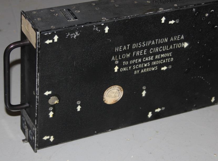
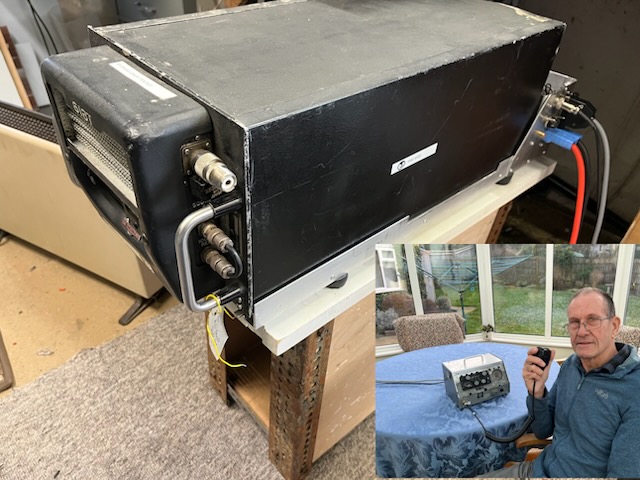
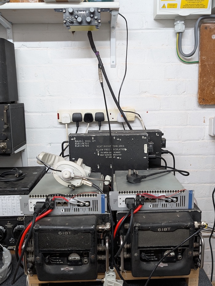
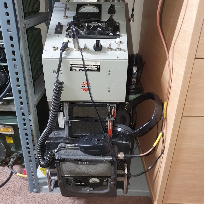
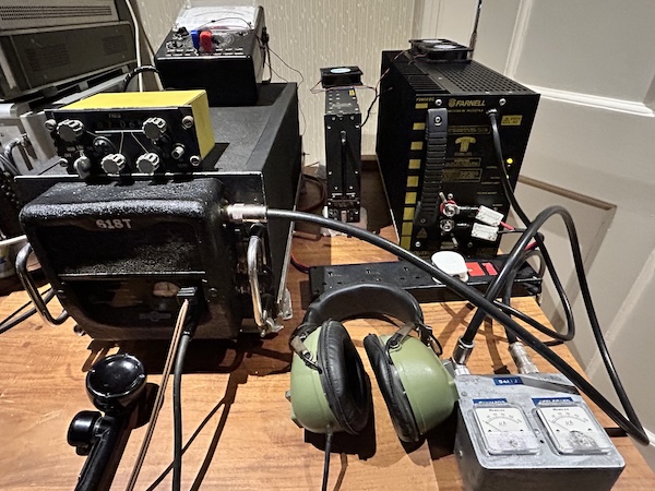
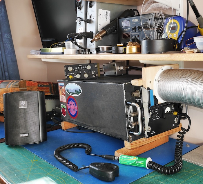
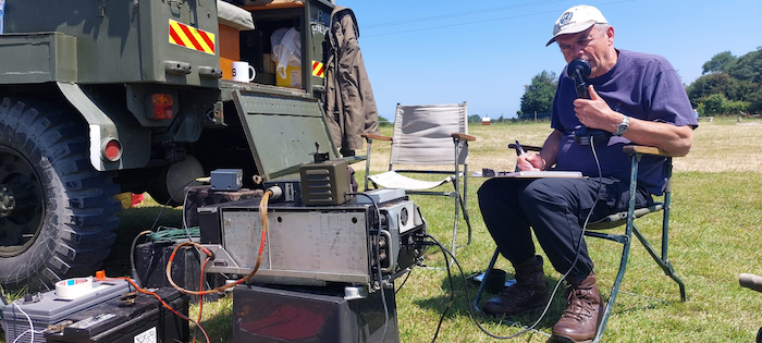
Most of the sets on the surplus market are the 618T-3, which runs off 28 VDC, but also needs a small amount of 115 V 400 Hz power. This seems to be the most popular of the sets in use in the amateur community and is probably the easiest to get on the air. The minimum number of parts needed to get this set up and running are the set itself, the rear connector and an earthing-pin, and the control box and its connector. Power needed is 28 VDC at 35 A and 115 VAC 400 Hz at around 1 A. Although the set is designed to be installed in a mounting tray, it can be used without one, just as long as there is a space under the set for cooling air from the fan to flow out of the set.
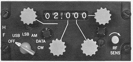
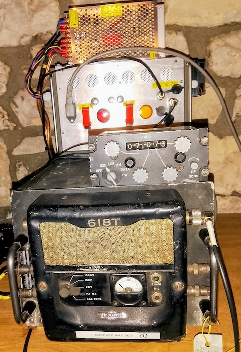
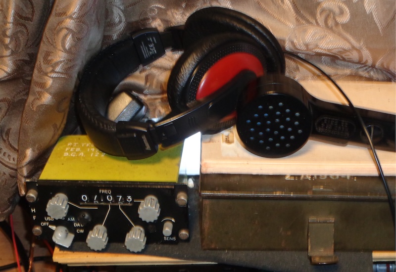
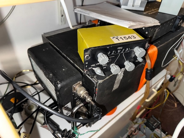
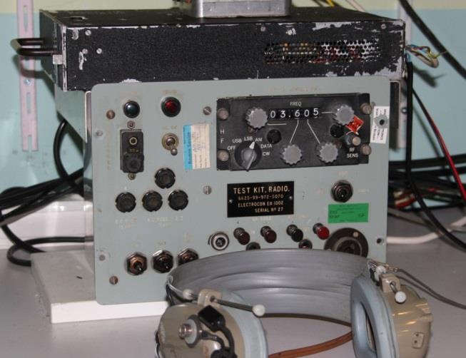
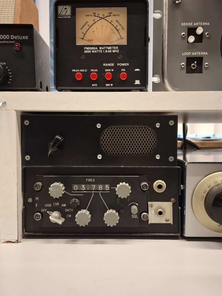
The 714E-3 Control Panel
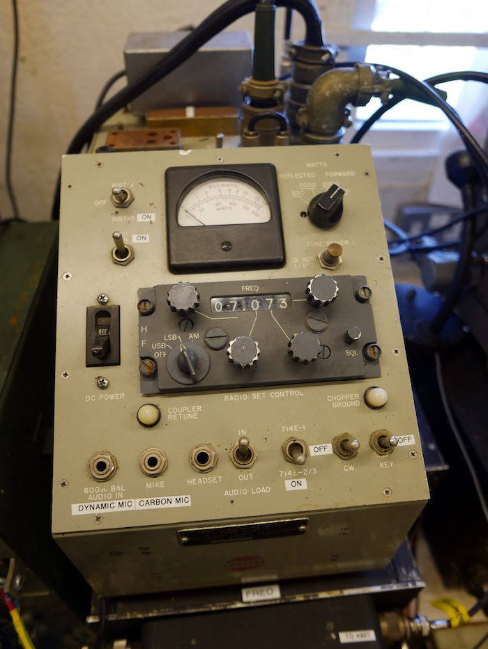
The 618T is remotely controlled by the 714E radio set control. The panel contains all controls necessary for frequency selection of any one of the 28,000 channels. The panel provides direct readout of frequency and permits selection of the mode of operations: upper or lower sideband or AM operation. The 714E has a back light. There is a RF sensitivity knob on the panel to control the RF sensitivity in all operating modes except data. Sensitivity is set to maximum when using data operation mode. The 714E-3 control panel used a Bendix 39-pin connector, PT06A-20-39S(SR) or MS3116A-20-39S.
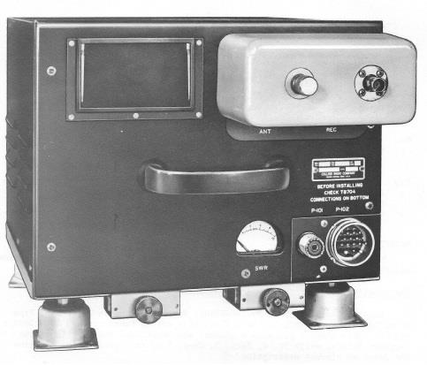
Antenna Tuner
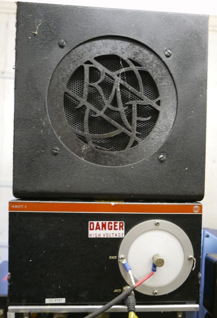
The 618T was designed to work with automatic antenna tuners such as Collins 180L3 or 490T-1 for antenna adjustments in airborne environment. It is however possible to use the 618T with any other 50 Ω antenna tuner. In fact, it can be rather frustrating using one of the Collins tuners, as in one configuration, the ATU retunes every time the frequency is changed. Also note that the 180L3 tuner only covers frequency range 2 to 22MHz and that the tuning time can take between 5 to 30 seconds.
The tuned circuits and outputs circuits of the 618T are tuned automatically by an internal Autopositioner and a servo motor. The 618T can handle SWR up to 1.3:1 meaning that an external tuner may be optional if you have a 50 Ω antenna and an SWR less than 1.3:1. The average tuning time of the 618T is 8 seconds.
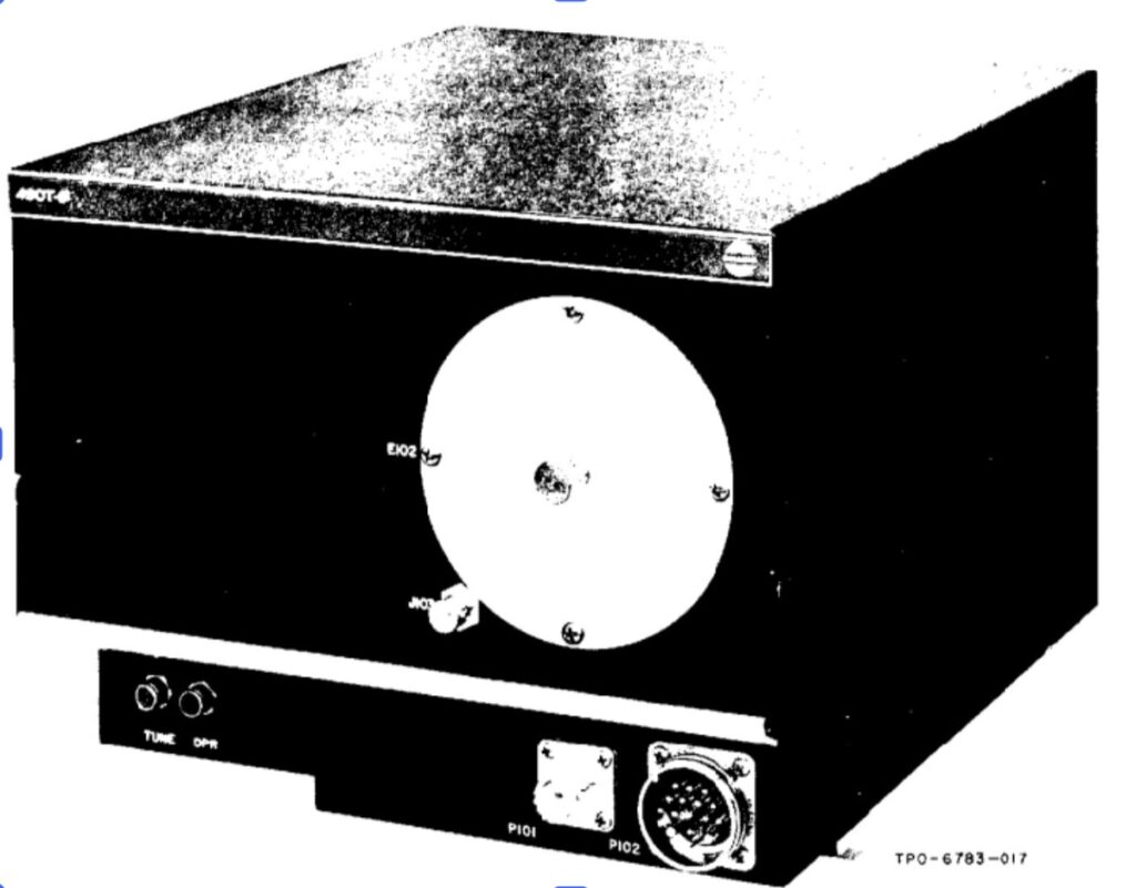
Below are the Collins 180L3 and 490T-1 automatic tuners. The automatic tuners were developed to automatically match a fixed wire or long wire antenna to a 50 Ω nominal transmitter output impedance. The table below provides a brief comparison of the main characteristics of the Collins 180L3 and 490T automatic tuners.
| ATU Characteristics | Collins 180L3 | Collins 490T-1 |
|---|---|---|
| Design to match | Any fixed wire antenna between 45 to 100 feet in length | 25 feet or longer whips and wire antennas |
| Frequency range | 2-22 MHz | 2-30 MHz |
| RF power levels | 500 W PEP or 180 W average | 650 W PEP or 200 W average |
| Tuning time | 5-30 seconds | 2-3 seconds |
| Input impedance | 50 Ω | 50 Ω |
| Power requirements | 27.5 V, 3.5 A max; 115 V, 400 Hz, 1 phase, 20 VA max; 250 VDC, or 400 VDC, 35 mA max. | 115 V, 400 Hz, 1 phase, 130 W max during tuning, 20 W during operate |
| Weight | 9.53 kg | 8.48 kg |
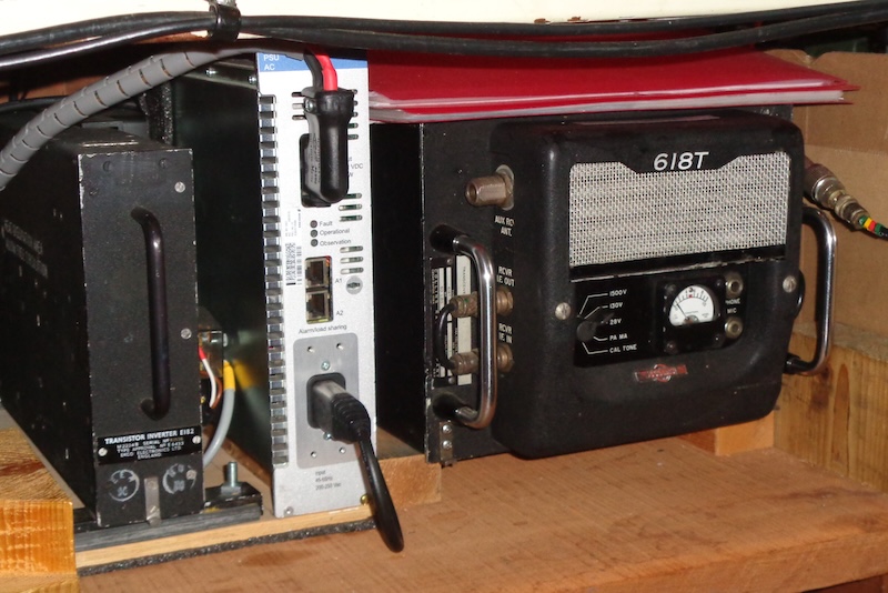
115 VAC 400 Hz power supply
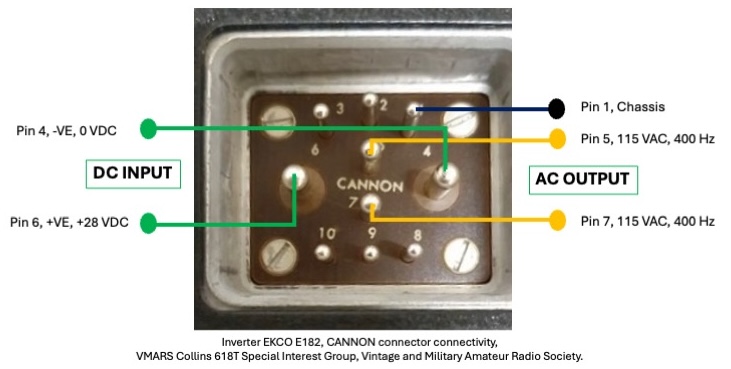
The EKCO E182 is one of the many inverters suitable for producing the 115 VAC 400 Hz power needed for the 618T-3. This inverter was used extensively in RAF aircraft. This is needed to drive the fan and some of the motors in the power amplifier. The static inverter is designed to provide a 115 V at 400 Hz single phase AC output from a nominal 28 VDC power supply. The inverter can supply up to 150 VA under full load according to the manual. Click here to access the manual and schematic of the EKCO E182 inverter. The inverter was manufactured by “EKCO”. EKCO is an abbreviation from “Eric Kirkham Cole” Limited. EKCO was a British electronics company founded by Eric Kirkham Cole in Southend-on-Sea during 1924.
The E182 inverter uses a 10-way CANNON connector at the rear end of the case. The connectivity pinout is shown in the Figure below.
Interconnecting the 618T-3
Surprisingly, to wire up a harness to connect it together and make a working system takes just a couple of hours, using one of the aircraft installation diagrams. This assumes of course that some suitable wire for the harness is available, American AWG 20 or equivalent. All electrical connections are made at a 60-pin, CANNON DPE-60-33s, connector located at the rear of the unit. The Figure below provides a high-level overview of the interconnection setup for the 618T.
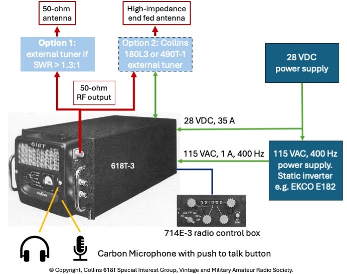
Click here to access a high resolution interconnect diagram for the 618T. This document is made available by VMARS. VMARS distributes this material under fair-use permission granted by the Collins Collector Association.
Microphones and Headphones
In the aircraft, the set would be wired to the intercom, and used via it. However, to make life easy, there is provision on the front panel for a microphone and headphones.
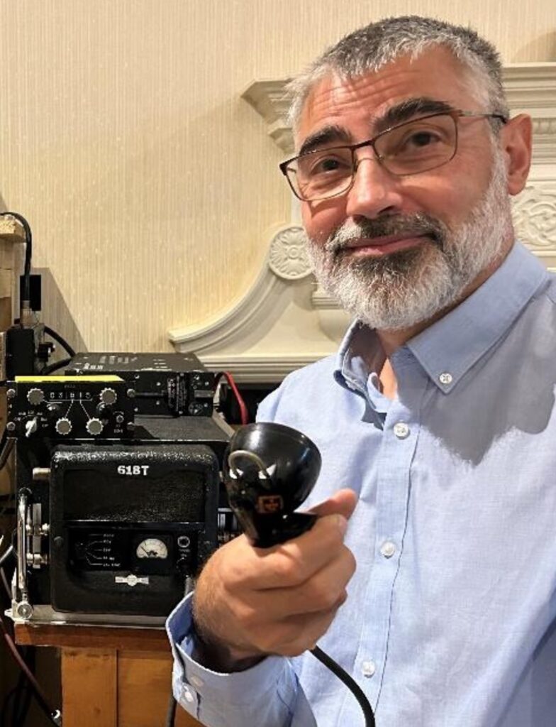
The microphone socket, which takes a PJ-68 jack plug, is designed for a carbon microphone. Any good carbon microphone should work, as long as it still has a DC resistance of around a few hundred Ω. The microphone interface also has provision for a PTT switch to key the transmitter.
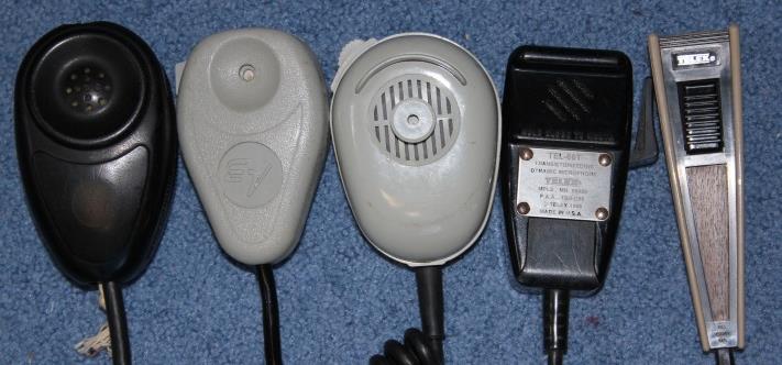
The microphone interface is the same as the one in use in light aircraft, and so any hand microphone for a light aircraft, such as those shown here, is suitable. There is a socket for headphones with a PL-55 Jack plug. This can accommodate headphones with impedances in the range 150 to 600 Ω. Hidden underneath the removable front cover is a pre-set headphone volume control and a pre-set side-tone volume control. An aircraft headset with PL-55 and PJ-68 connectors, with a carbon equivalent microphone will work with the set, but then an additional PTT switch is needed, as aircraft headsets usually do not have a PTT switch. It is possible to provide PTT switch provision via some additional wiring to the 60-pin connector at the rear of the 618T.
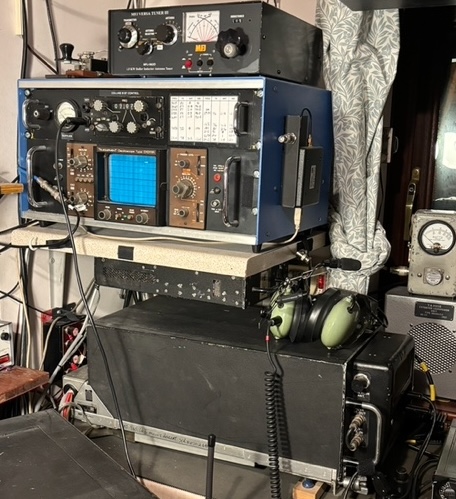
On the air
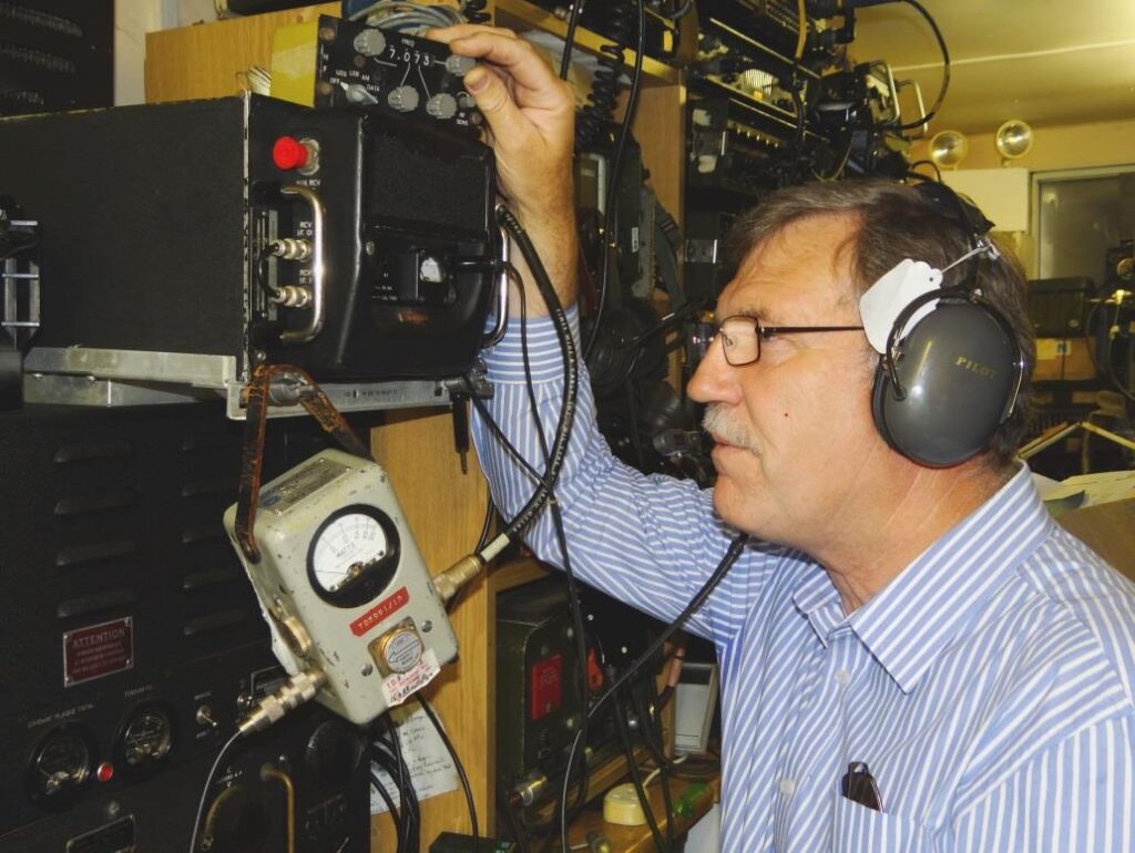
The set works well in the amateur environment. It tunes in 1 kHz steps, but that does not seem to be much of a problem. Scanning across the band is not too easy, but once on the air and in a QSO, the set performs very well, and almost always gets a good report.
The VMARS SIG runs a regular net to discuss technical issues. The Net is operated by VMARS member, Trevor, PA3BOH, in Wassenaar, Netherlands. The net is at 12:00 UK time on Wednesdays on 7073 kHz in lower side band (LSB) +/- QRM or a bit lower in frequency if it is busy.
In the Netherlands, the CRASH museum, with members of the Dutch Surplus Radio Society, used a 618T in the past for special events and as a club station, with the following call-signs: PI9CRASH, PI9SPITFIRE, and PI4C. One other station regularly on the air in the Netherlands with a 618T is the KLM Radio Club’s station, PI9KLM.
Documentation
The best place to access the Collins manuals and schematics is the Collins Collectors Association (CCA) web site at https://collinsradio.org/cca-collins-technical-archives/collins-radio-equipment-manuals/ ; The CCA web site has several revisions of the manual from 1962, 1973 and 1978. All these manuals are complementary.
618T UK stations
Alan, G4MOM
Glyn, M3ZLA

Ian, G3WXG
Ian, G6TVJ
John, 2E0KNJ
John, M0BIC
Justin, GW0FZY
Keith, G8ELA
Kevin, G0EBL
TBD
Les, 2E0IBN
Ray, G6RAY
Richard, M1CFW
Stuart, G0TBI
Thierry, M1DRT
Tom, G4KWL
618T Dutch stations
Anton, PE1JAS
CRASH40-45 Museum, PI4C
Gerrit, PA0GJC
Herman, PH1DTC
Trevor, PA3BOH
PI9KLM, KLM Royal Dutch Airlines
List of selected technical articles published in Signal
Signal is the Journal of the Vintage and Military Amateur Radio Society. Click here for more information about Signal.
- Thierry Delaitre (M1DRT), Collins 618T3 Restoration, Issue. 76, pp. 49–57, August 2025.
- Richard Powell (M1CFW), A 618T Tidy Up, Issue. 53, pp. 22, November 2019.
- John Keeley (G6RAV), The Collins 618T, Part 3, Issue. 24, pp. 27–38, August 2012.
- Trevor Sanderson (PA3BOH/G4OEY), 618T Signal Fadeout on 9th May 2012, Issue. 24, pp. 13–14, August 2012.
References
- Collins Signal, Product Bulletin Publication, Volume VIII, Number 3, 1960, Collins 618T product profile, pp. 24, https://collinsaerospacemuseum.org/collins_signal/viewer.php?i=s360&m=28&r=16&z=1&p=24
- Collins manuals, Collins Collectors Association, https://collinsradio.org/cca-collins-technical-archives/collins-radio-equipment-manuals/
- EKCO E182 static inverter manual, https://scottbouch.com/rtfm/volume/ap/4343/b/v1/s18/ap4343b-v1-s18-c16-al81.pdf
Collins 618T QSO Net Archive
Audio recording of a part of the Collins SIG Net held on 11th June 2025 on 40 m, 7073 KHz LSB, during the D-Day expedition to France by some VMARS Members. The Net controller is Trevor, PA3BOH. Martin Smyth, M0MGA, is taking an over with Thierry, M1DRT, located in London. The Net is operated from the Radar Museum in Douvres in Normandy using the special event callsign TM81SR (Station Radar). The QSO was recorded using a WebSDR located in Weston-Super-Mare, South West UK, England from G8JNJ.
Document Maintenance and Contributions
This Collins 618T Special Interest Group document is maintained by the VMARS Web Editor and relies on member contributions to remain current and accurate.
Members wishing to submit:
- Updates or corrections to existing content
- New information relating to Collins 618T equipment or operation
- Photographs of Collins 618T transceivers, installations, or associated equipment
should forward these items to the VMARS Web Editor using this address webeditor (at) vmars.org.uk for review and inclusion.
Submissions should include the contributor’s callsign and any relevant descriptive information. Submission of photographs implies permission for VMARS to display the images on the VMARS website in connection with the Collins 618T SIG.
Disclaimer
VMARS is not responsible for any statements made on this page or for any issues, errors, or outcomes resulting from its use.